


Initial situation
In the current regulations and guidelines for the installation of windows and window sills, in some cases, no exact details are given for the sealing of union connections. Due to the resulting imperfections, water can penetrate into the wall structure during extreme rainfall events and cause moisture damage, especially in the case of ecological insulation materials.
A test method for being able to test sealing measures in practice does not exist. The test methods with driving rain with pulsating air pressure according to DIN EN 12865 for external wall systems and DIN EN 13050 for curtain wallings are not suitable for this purpose.
Determination of the resistance for driving rain
The test setup to determine the watertightness consists of 2 components:
1) Device for driving rain load
To simulate driving rain events, a fan with adjustable air nozzle (diameter 300 mm) was installed on a stand. With this device, wind speeds up to about 140 km/h or a wind pressure of up to about 950 Pa can be generated (see figure 1).
Above the air nozzle (jet), water spray nozzles are installed to readjust a rain load of approx. 2 l / (min m²).
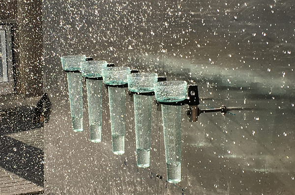
The simulation of the driving rain took place in which the drops of water produced by the water spray nozzles are thrown by the wind from the jet to the facade surface. The generation of the driving rain is shown as an example in figure 2.
2) Test rig
To build the sealing measures to be tested is a metal frame with perforated plates for simulating a window opening in the wall or timber frame. In this window section windows are practically installed with a sill or roller shutter box.
As a window sill, a grate with an underlying tray is used to catch any penetrating water (see figure 3).
With the experimental setup of these two components (see figure 4) reproducible driving rain loads can be carried out. The following test parameters can be controlled:
- Wind speed or wind load
- Rain load (flow rate and water pressure)
- defined routes and speed of the jet
- Variation of the jet angle (vertical and horizontal) to the facade surface
- Distance of the jet to the facade surface
The performance of a driving rain load is shown in figure 5.
Due to the permanent movement of the jet, a variety of turbulence effects arise temporarily at points to be tested, as they also occur in practice (see figure 6).
After completion of the driving rain load, the tested construction is examined for penetrated water. For this purpose, water may only be present in areas which serve for the controlled removal of water. In addition, no water must be caught in the tray below the grate during and after completion of the driving rain load.
If you have any questions please don’t hesitate to contact
Mr. Michael Vonrhein Mr. Philipp Kröber
(+49)6154-71-71378 or (+49)6154-71-72495